Free NCERT Solutions for Class 12 Physics Chapter 15 Communication Systems solved by Expert Teachers as per NCERT (CBSE) Book guidelines and brought to you by CBSE Learning. These Communication Systems Exercise Questions with Solutions for Class 12 Physics covers all questions of Chapter Communication Systems 12 and help you to revise complete Syllabus and Score More marks as per CBSE Board guidelines from the latest NCERT book for class 12 Physics. You can read and download NCERT Book Solution to get a better understanding of all topics and concepts
15.1 – INTRODUCTION
15.2 – ELEMENTS OF A COMMUNICATION SYSTEM
15.3 – BASIC TERMINOLOGY USED IN ELECTRONIC COMMUNICATION SYSTEMS
15.4 – BANDWIDTH OF SIGNALS
15.5 – BANDWIDTH OF TRANSMISSION MEDIUM
15.6 – PROPAGATION OF ELECTROMAGNETIC WAVES
15.6.1 – Ground wave
15.6.2 – Skywaves
15.6.3 – Space wave
15.7 – MODULATION AND ITS NECESSITY
15.7.1 – Size of the antenna or aerial
15.7.2 – Effective power radiated by an antenna
15.7.3 – Mixing up of signals from different transmitters
15.8 – AMPLITUDE MODULATION
15.9 – PRODUCTION OF AMPLITUDE MODULATED WAVE
15.10 – DETECTION OF AMPLITUDE MODULATED WAVE.
Communication Systems NCERT Solutions – Class 12 Physics
Class 12th Physics Chapter 15 Communication Systems NCERT Solution is given below.
Question 15.1: Which of the following frequencies will be suitable for beyond-the-horizon communication
using sky waves?
(a) 10 kHz
(b) 10 MHz
(c) 1 GHz
(d) 1000 GHz
Answer
(b) 10 MHz
For beyond-the-horizon communication, it is necessary for the signal waves to travel a large distance. 10 KHz signals cannot be radiated efficiently because of the antenna size. The high energy signal waves (1GHz − 1000 GHz) penetrate the ionosphere. 10 MHz frequencies get reflected easily from the ionosphere. Hence, signal waves of such frequencies are suitable for beyond-the-horizon communication.
Question 15.2: Frequencies in the UHF range normally propagate by means of:
(a) Ground waves.
(b) Sky waves.
(c) Surface waves.
(d) Space waves.
Answer
(d) Space waves
Owing to its high frequency, an ultra high frequency (UHF) wave can neither travel along the trajectory of the ground nor can it get reflected by the ionosphere. The signals having UHF are propagated through line-of-sight communication, which is nothing but space wave propagation.
Question 15.3: Digital signals
(i) Do not provide a continuous set of values,
(ii) Represent values as discrete steps,
(iii) Can utilize binary system, and
(iv) Can utilize decimal as well as binary systems.
Which of the above statements are true?
(a) (i) and (ii) only
(b) (ii) and (iii) only
(c) (i), (ii) and (iii) but not (iv)
(d) All of (i), (ii), (iii) and (iv).
Answer
(c) is true.
A digital signal uses the binary (0 and 1) system for transferring message signals. Such a system cannot utilize the decimal system (which corresponds to analogue signals). Digital signals represent discontinuous values.
Question 15.4: Is it necessary for a transmitting antenna to be at the same height as that of the receiving antenna for line-of-sight communication? A TV transmitting antenna is 81m tall. How much service area can it cover if the receiving antenna is at the ground level?
Answer
Line-of-sight communication means that there is no physical obstruction between the transmitter and the receiver. In such communications it is not necessary for the transmitting and receiving antennas to be at the same height.
Height of the given antenna, h = 81 m
Radius of earth, R = 6.4 × 10⁶ m
For range, d = (2Rh)½, the service area of the antenna is given by the relation:
A = πd2
= π (2Rh)
= 3.14 × 2 × 6.4 × 106 × 81
= 3255.55 × 106 m2
= 3255.55
~3256km2
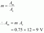
Question 15.5 : A carrier wave of peak voltage 12 V is used to transmit a message signal. What should be the peak voltage of the modulating signal in order to have a modulation index of 75%?
Answer :
Amplitude of the carrier wave, Ac= 12 V
Modulation index, m = 75% = 0.75
Amplitude of the modulating wave = Am
Using the relation for modulation index:

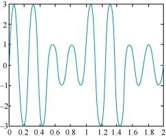
Question 15.6 : A modulating signal is a square wave, as shown in Fig. 15.14.
 The carrier wave is given by c(t)=2sin(8πt)volts.
(i) Sketch the amplitude modulated waveform
(ii) What is the modulation index?
Answer :
It can be observed from the given modulating signal thatthe amplitude of the modulating signal, Am= 1 V
It is given that the carrier wave c(t) = 2 sin (8πt)
∴Amplitude of the carrier wave, Ac= 2 V
Time period of the modulating signal Tm= 1 s
The angular frequency of the modulating signal is calculated as:
 The angular frequency of the carrier signal is calculated as:
![]() From equations (i) and (ii), we get:
From equations (i) and (ii), we get:
![]() The amplitude modulated waveform of the modulating signal is shown in the following figure.
The amplitude modulated waveform of the modulating signal is shown in the following figure.
 (ii)Modulation index,
![]()
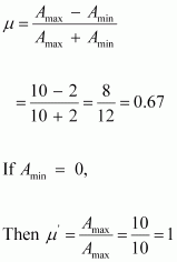
Question 15.7 : For an amplitude modulated wave, the maximum amplitude is found to be 10 V while the minimum amplitude is found to be 2 V. Determine the modulation index μ. What would be the value of μ if the minimum amplitude is zero volt?
Answer :
Maximum amplitude, Amax= 10 V
Minimum amplitude, Amin= 2 V
Modulation index μ, is given by the relation:

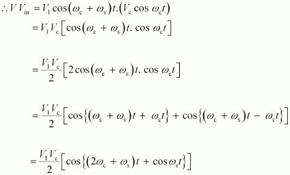
Question 15.8: Due to economic reasons, only the upper sideband of an AM wave is transmitted, but at the receiving station, there is a facility for generating the carrier. Show that if a device is available which can multiply two signals, then it is possible to recover the modulating signal at the receiver station.
Answer
Let ωc and ωs be the respective frequencies of the carrier and signal waves.
Signal received at the receiving station,V= V1cos (ωc+ωs)t
Instantaneous voltage of the carrier wave, Vin = Vc cos ωct
 At the receiving station, the low-pass filter allows only high frequency signals to pass through it. It obstructs the low frequency signal ωs.
Thus, at the receiving station, one can record the modulating signal ![]() which is the signal frequency.
which is the signal frequency.